With the possible exception of
kinetically charged flywheels, energy storage technologies, discussed thus far,
have used electricity as the primary form of energy to charge the storage device.
In all cases the output of the storage device, during discharge, has been
electricity. Other forms of energy can be the input and output of a storage
device. In the case of thermal energy storage, the charging and sometimes
discharging of the device involves the transfer of heat. Just like other
storage technologies, there is great variability in energy storage metrics that
characterize the device and the device’s application.
One form of thermal energy storage,
common as a "passive design" practice for the built environment, is
to add thermal mass onto a building to buffer indoor temperatures against
dramatic shifts in outdoor temperature. Sometimes called a "thermal
flywheel" because of its ability to smooth out temperature variation, thermal
mass can have a dramatic impact on the amount of energy used to heat or cool a
building. Thermal mass is simply a solid or liquid that will absorb and store
warmth, often from direct sunlight, so that the heat can be released indoors
when outdoor temperatures fall. Thermal mass implementations have also been
used to store "coolness" by releasing heat to reach a lower
temperature and then absorbing heat at a later time to reduce indoor
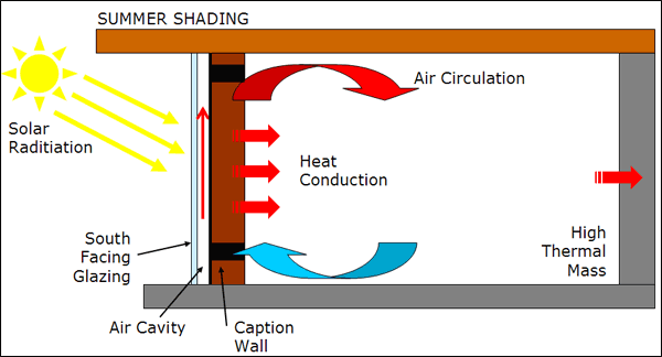
temperatures relative to the warmer outside temperatures (Torcellini & Pless, 2004) . Figure
1
shows a diagram of a common thermal mass building element called a “Trombe
wall”. A well installed Trombe wall can dramatically reduce the climate control
energy needs of a building (DWLS, 2008) .
Thermal energy storage can also be
used to generate and store electricity. Concentrated solar thermal - CST -
power plants use parabolic mirrors, called heliostats, which track the sun as
it passes through the sky to concentrate sunlight. In some applications, a
large array of two-axis heliostats concentrates the sunlight to a central point
in the power plant to heat a generating fluid. In other applications the fluid
is heated in a pipe located at the focal point of each single axis heliostat (Solúcar,
2006) .
Steam is generated, either directly, when water is the generating fluid, or
indirectly, when other substances are used. This steam turns a steam turbine
that powers a generator producing electricity. Some of the heated generating
fluid is stored for later use. This allows the CST to compensate for variations
in solar access caused by clouds while also providing the ability to produce
power at night. Depending on the generating fluid and system design, the night
time discharge duration can be several hours. Figure
2
shows a diagram of the PS-10, a 10MW solar thermal power plant located near
Seville, Spain. The PS-10 uses water/steam as the generating fluid and has a
storage capacity equivalent to 20 MWh (Solúcar, 2006) .
Figure 2 showing a diagram of the PS-10, a 10MW
thermal power plant near Seville, Spain, with a thermal storage capacity
equivalent to 20 MWh (Solúcar,
2006) .
Recently,
the world’s largest parabolic trough Concentrated Solar Power plant with
thermal energy storage, built in Gila Bend, Arizona, passed commercial
operation tests. Though similar in some respects to the plant shown in Figure
2
this massive 280 MW facility uses parabolic mirrors to concentrate sunlight to a
pipe containing a heat transfer fluid (synthetic oil) that passes through the
focus of the parabolic mirror. Ultimately water is heated by the heat transfer
fluid to become steam to drive a turbine. A reservoir of heated oil is used to
store excess thermal energy. This stored thermal energy can be used to drive
the turbines at full power (280 MW) for six hours (Owano, 2013) .
In
all but the coldest climates, energy used to provide air conditioning can
represent a sizable portion of a building’s electricity consumption. Thermal
energy storage, such as Ice Energy’s Ice Bear distributed thermal energy
storage system, can be used to augment traditional air conditioners to make
them more efficient. The Ice Bear is essentially a large thermal storage tank
where ice is produced at night during off peak periods (Figure
3).
This not only takes advantage of cheaper off peak energy, it also improves the
overall efficiency of the system as nighttime temperatures are lower, requiring
less energy to produce the ice. During peak daytime periods, when AC energy
consumption is high, water chilled by the ice is used to cool the AC unit’s
refrigerant instead of the unit’s compressor. The “discharge” cycle of the Ice
Bear is at least 6 hours. The unit is also advertised as being a “lossless”
storage system because the Ice Bear improves the operating efficiency of the AC
unit to a point that “more than compensates for any inherent inefficiencies in
the storage/discharge cycle common to other types of energy storage.” (Ice Energy,
2012)
The Ice Bear is rated to provide a 7 kW reduction in peak power demand with a
total of 35 kWh of energy shifted to off peak with a 25 year design life (Ice Energy, 2012) .
Figure 3 showing Ice Energy’s Ice Bear thermal
energy storage system used to augment an existing building AC unit (Ice Energy,
2012) .
Works Cited
DWLS. (2008). Design Examples | Druk White Lotus
School, Ladakh. Retrieved January 20, 2013, from www.dwls.org:
http://www.dwls.org/Sustainable-Design-Examples.html
Ice Energy. (2012). Product Sheet; Ice Bear Energy
Storage. Windsor, CO: Ice Energy.
Owano, N. (2013, October 11). Arizona solar plant
achieves six hours after sun goes down. Retrieved October 17, 2013, from
phys.org: http://phys.org/news/2013-10-arizona-solar-hours-sun.html
Solúcar. (2006). 10 MW Solar Thermal Power Plant
for Southern Spain. Seville, Spain: Solúcar.
Torcellini , P., & Pless, S. (2004). Trombe
Walls in Low-Energy Buildings: Practical Experiences. Golden, CO: National
Renewable Energy Laboratory .


No comments:
Post a Comment