Friday, September 27, 2013

Lithium-Ion Batteries

Small lithium-ion batteries are quite popular in mobile electronics applications and also for use as drive batteries for hybrid and plug-in electric vehicles. Lithium-ion batteries have a very high charge density with a comparatively light weight. They can handle a large number of charge and discharge cycles with very low energy dissipation (i.e. high energy retention time) before discharge. These batteries also have a high round trip efficiency between 85% to 90% (Abele, Elkind, Intrator, & Washom, 2011).
Lithium-ion batteries would seem ideal for energy storage if not for their current limitations. Lithium is considered to be a rare metal with limited global availability. Lithium is also highly reactive in water and air requiring that the batteries be sealed from the environment with many internal mechanisms to protect against pressure buildup and power surges (Abele, Elkind, Intrator, & Washom, 2011). Lithium-ion batteries also “age” or degrade even when not in use. There is noticeable capacity deterioration after one year, with many batteries failing after two or three years (Battery University, 2010).
               Lithium-ion batteries consist of a positive electrode made of Lithium cobalt oxide (LiCoO2) and a negative electrode made of carbon (C). They are separated by a thin micro-perforated plastic sheet that allows the ions to pass between electrodes (Battery University, 2010). This creates the flow of electricity during discharge (Figure 1).


Figure 1 basic diagram of a lithium-ion battery during discharge.

While charging, the electron flow is reversed; the overall chemical reaction is:

(Panasonic, 2007).

Though the energy density of lithium-ion batteries is ideal, the limitations of this technology have mostly kept lithium-ion batteries out of consideration for large scale energy storage. Of course with energy storage, change is the only constant. Very recent developments have started to show promise for lithium-ion batteries in smaller scale energy storage applications. One example involves repurposing the spent lithium-ion batteries from the Chevrolet Volt automobile to store energy in a 25-kW, 50-kWh energy storage device. Once the Volt drive batteries lose 30% of their capacity they are no longer valid as drive batteries for the automobile. However, the remaining 70% of capacity can be used for smaller scale storage applications (Danko, 2012). Other examples include the development of containerized lithium-ion storage units such as the Saft, Intensium Max, which is aimed towards applications to support wind or solar electricity generation. These units have an energy rating in the 400 kWh to 600 kWh range.  Future developments that address the limitations of lithium-ion batteries will likely move this technology further towards mainstream large scale energy storage (Saft, 2012).
The high power-to-weight ratio of lithium-ion batteries has, in recent years, made them very appealing in the aerospace industry. In the Boeing 787 Dreamliner, the use of lithium-ion batteries is part of what makes the plane lighter and 20% more fuel efficient than its predecessors. Unfortunately in January of 2013 the entire fleet of 787's was grounded primarily because the lithium-ion batteries have been igniting and releasing smoke into the cabin (Bennet, 2013).

Works Cited

Abele, A., Elkind, E., Intrator, J., & Washom, B. (2011). 2020 Strategic Analysis of Energy Storage in California. Los Angeles: California Energy Commission. Publication Number: CEC-500-2011-047.

Battery University. (2010). Is Lithium-ion the Ideal Battery? Retrieved January 7, 2013, from Battery University: http://batteryuniversity.com/learn/article/is_lithium_ion_the_ideal_battery

Bennet, D. (2013, January 18). Why Are the Batteries in Boeing's 787 Burning? Retrieved January 19, 2013, from Bloomberg Businessweek Technology: http://www.businessweek.com/articles/2013-01-18/why-the-batteries-in-boeings-787-are-burning

Danko, P. (2012, November 19). Old Volt Batteries: Out Of The Car, Into The Home? Retrieved January 7, 2013, from Earth Techling: http://earthtechling.com/2012/11/old-volt-batteries-out-of-the-car-into-the-home/

Panasonic. (2007). Lithium Ion Batteries. Osaka: Panasonic.

Saft. (2012, April). Intesium Max. Retrieved January 7, 2013, from Saft Batteries: http://www.saftbatteries.com/doc/Documents/aviation/Cube946/C081_3-Intensium%20MaxContainer_EN%20-%20PROTEGE.7507d077-584f-4845-8d96-cfb6fed53fc6.pdf


Thursday, September 26, 2013

Lead-Acid Batteries

Conceivably the most popular application for lead-acid batteries is as the power source for the starter in an automobile. In stationary storage applications, lead-acid batteries are also used to provide uninterruptible power supply (UPS) service to datacenters and even island grid support for small scale distributed renewable energy applications. There are an estimated 95,000 lead-acid battery arrays deployed in the US at utility substations to provide blackout and black start grid support (Eyer & Corey, 2010).  First invented in 1859 by Gaston Planté, lead-acid batteries are the most prevalent form of energy storage today (EPRI, 2003).
               Lead-acid batteries consist of alternating plates of lead (Pb) and lead oxide (PbO2), that form the electrodes. The electrodes are submerged in a liquid or gel electrolyte solution of sulfuric acid (H2SO4). During discharge the lead anode gives up electrons that the lead oxide cathode accepts. This creates the flow of electricity (Figure 1). During discharge both plates begin to accumulate lead sulfate (PbSO4) (Hammack, 2012)


Figure 1 basic diagram of a lead-acid battery during discharge.

While charging, the electron flow is reversed and sulfate returns to the electrolyte making it stronger and increasing the charge of the battery (EPRI, 2003). The overall chemical reaction is:

(EPRI, 2003)


The buildup of lead sulfate on the electrodes can limit the ability for the battery to recharge. For this reason lead-acid batteries to be used in deep discharge applications (common for energy storage) must be designed with larger electrodes that are spaced further apart and must also include a reservoir to capture sulfate debris (Hammack, 2012). This results in an increase in size and weight. The bulky nature of lead-acid batteries results in relatively low ratio of energy to size; i.e. a low energy density. This low energy density significantly reduces their appeal for grid scale energy storage (Baxter, 2006).
               Though lead is considered poisonous to humans, its density makes it easy to separate from other materials when a battery is recycled. This ability to easily isolate lead, coupled with the fact that lead-acid batteries are so pervasive, makes lead-acid battery recycling a profitable endeavor such that 96% of all lead-acid batteries are recycled. Even the spent electrolyte is recaptured through acid reclamation. 60% to 80% of each new battery contains recycled lead or plastic (US EPA, 2012).

Works Cited

Baxter, R. (2006). Energy Storage; A Nontechnical Guide. Tulsa, Oklahoma: PennWell Corporation.

EPRI. (2003). EPRI-DOE Handbook of Energy Storage for Transmission & Distribution Applications. Washington DC: EPRI, Palo Alto, CA, and the U.S. Department of Energy.

Eyer, J., & Corey, G. (2010). Energy Storage for the Electricity Grid: Benefits and Market Potential Assessment Guide. Albuquerque, New Mexico: Sandia National Laboratories.

Hammack, B. (2012, July 3). How a Lead-Acid Battery Works. Retrieved January 6, 2013, from Engineer Guy: http://www.youtube.com/watch?v=rhIRD5YVNbs&feature=youtube_gdata_player

US EPA. (2012, November 19). Batteries. Retrieved January 6, 2013, from US EPA: http://www.epa.gov/osw/conserve/materials/battery.htm


Basic Components of an Energy Storage System

In its most basic form, energy storage absorbs energy to be released at a later time. Most commonly, the input and output to the energy storage system is electricity but systems that store heat and kinetic energy also exist. Each energy storage unit or facility is made up of three subsystems: the storage medium, the power conversion system and the balance of the plant (Baxter, 2006). A description of each subsystem is as follows:
·        Storage Medium – the storage medium is the reservoir in which energy, in an energy storage system, is stored. The energy can be stored in the form of chemical energy, electrochemical energy, electrical energy, mechanical energy and thermal energy. The energy density of the storage medium often dictates the size of the storage device relative to its desired power and energy output. Low energy density, high power storage devices tend to be physically larger than high energy density, low power storage devices. Generally accounting for one half the cost of the storage unit, the cost of the medium is divided into the capital cost of the medium and the cost of maintaining the medium in a charged state (Baxter, 2006).
·        Power Conversion System (PCS) – is the interface between the storage medium and the end user of the storage system’s output. If the output is electrical, the PCS will need to not only convert the power from the storage medium but also condition the electricity so that it is appropriate for consumption. Often, the PCS is also used to charge the energy storage medium. The PCS can often account for greater than 25% of the cost of the storage unit; more commonly in the range of 33% to 50% (Sandia Corporation, 2012).
·        Balance of Plant (BOP) – the BOP is essentially the components of the storage unit that are not the storage medium or the PCS. The BOP can include equipment to control the environment of the storage medium and the PCS, equipment to house and shelter the storage device, and other equipment necessary for operation. BOP tends to be the most variable component cost across energy storage devices, representing the remainder of costs after the storage medium and PCS. The BOP is typically in the range of 10% to 30% of the overall device costs (Baxter, 2006).

Works Cited

Baxter, R. (2006). Energy Storage; A Nontechnical Guide. Tulsa, Oklahoma: PennWell Corporation.

Sandia Corporation. (2012). Energy Storage Systems - Technology; Power Electronics. Retrieved January 5, 2012, from Sandia National Laboratories: http://www.sandia.gov/ess/tech_power.html


Sunday, September 1, 2013

Application 9: Reliability and Power Quality

Companies that employee sophisticated, sensitive, digital equipment or those engaged in continuous process manufacturing can be severely impacted by power outages and incidents of reduced power quality. “Across all business sectors, the U.S. economy is losing between $104 billion and $164 billion a year to outages and another $15 billion to $24 billion to PQ (power quality) phenomena” (Lineweber & McNulty, 2001). In the same way that large scale energy storage can help a utility avoid power outages and degradations to power quality, end users can ride through outages and maintain power quality by employing energy storage on a smaller, more distributed scale. The investment in energy storage can be largely offset by reducing or eliminating lost productivity or equipment damage caused by these power quality events (Baxter, 2012)

Works Cited

Baxter, R. (2012, November 28). Author, Energy Storage; a Nontechnical Guide. (M. Banta, Interviewer)


Lineweber, D., & McNulty, S. (2001). The Cost of Power Disturbances to Industrial & Digital Economy Companies. Madison, WI: EPRI.

Application 8: Demand Charge Management

Demand charge management can be tied very closely with TOU energy cost management. By discharging an energy storage device during peak periods an end-user would also realize a financial benefit by decreasing the maximum power drawn during the billing cycle. Decreasing the maximum power would in turn decrease the demand charge applied by the utility to the end-user (Denholm P. , Ela, Kirby, & Milligan, 2010).
In TOU and demand charge management applications, the utility benefits with a more even load profile while end-users realize reduced electricity costs. It is important to note that some facilities employ thermal energy storage to reduce overall and peak electricity consumption by HVAC equipment (Ice Energy, 2012).

Works Cited

Denholm, P., Ela, E., Kirby, B., & Milligan, M. (2010). The Role of Energy Storage with Renewable Electricity Generation. Las Vegas: National Renewable Energy Laboratory.


Ice Energy. (2012). Product Sheet; Ice Bear Energy Storage. Windsor, CO: Ice Energy.

Application 7: Time of Use (TOU) Energy Cost Management

TOU Energy Cost Management, as a “behind the meter” application, is analogous to the utility scale time-shift application for energy storage in that it focuses on reducing peak energy consumption. In this application the energy storage device would be charged during less-expensive off-peak time periods. By discharging the device during more expensive peak periods, an end-user can reduce their electricity costs (Baxter, 2006).

Works Cited


Baxter, R. (2006). Energy Storage; A Nontechnical Guide. Tulsa, Oklahoma: PennWell Corporation.

Behind the Meter Applications

The applications of energy storage mentioned above generally serve large utility scale energy generation and distribution systems. These applications will be of critical importance if the future method of electricity generation and distribution is to follow the current model of the large centralized electric grid. The centralized large-scale generation model could also be supported by a distributed model of energy storage. Many of the challenges with large-scale energy storage (i.e. technical limitations, regulatory concerns, capital investment, land use etc.) can be circumvented by co-locating smaller scale energy storage systems with load sources (Wesoff, 2011). These applications are often referred to as “behind the meter” or “end-user” energy storage applications. Behind the meter applications provide benefits to grid operators by reducing demand and demand variability. End-users see benefits through reducing or modifying their reliance on the grid and also improving the reliability of their electricity supply.
An electric utility company profits from the consumption of its product, i.e. electricity. The most profitable, ideal and efficient scenario for a grid utility is one where electric demand remains predictable and constant with no variation. Utilities employ two billing schemes for larger, business customers in an attempt to discourage unpredictable consumption with significant time wise variation in power demand. The first billing scheme is to charge more for electricity consumed when demand is highest (i.e. the peak period) than the time period when demand is lowest (i.e. off peak period). The billing rates for peak and off-peak consumption are in units of $/kWh. The second billing scheme is to apply a “demand charge” measured in units of $/kW (Baxter, 2012). The demand charge is assessed by the highest demand of a customer (kW) in any 15 minute (or sometimes one hour) interval during a monthly billing cycle (NSTAR, 2013). This charge is levied even if there is only one such interval in the billing cycle. In many instances, the demand charge ($/kW) will rival the consumption charge ($/kWh) applied during a billing cycle.

Works Cited

Baxter, R. (2012, November 28). Author, Energy Storage; a Nontechnical Guide. (M. Banta, Interviewer)

NSTAR. (2013). Billing Rights. Retrieved January 21, 2013, from NSTAR: http://www.nstar.com/residential/customer_information/billing_rights.asp


Wesoff, E. (2011, May 25). Stealthy Small-Scale Storage Startups. Retrieved December 16, 2012, from greentechgrid: http://www.greentechmedia.com/articles/read/stealthy-storage-startups

Energy Storage Application 6: Transmission and Distribution Support

Energy storage can provide power quality and regulation support to the transmission and distribution (T&D) system in the same way that energy storage provides these services to the electricity generation side of the grid. Just as energy storage can be used to defer generation system upgrades, it can also be used to defer investment and upgrades to the T&D equipment (Eyer & Corey, 2010). T&D equipment upgrade deferral is a particularly good application for energy storage because often upgrades are needed to compensate for relatively modest power and energy increase requirements. Small modular energy storage systems can be deployed at locations in the T&D system where congestion or equipment failure is greatest, in order to cover demand peaks that usually happen only a few days a year. The alternative is often a large equipment investment with a capacity well beyond what is actually needed. The modest, incremental, storage investment would free up capital for other projects while improving utility asset utilization (Eyer & Corey, 2010)
It is interesting to note that there are nearly 100,000 lead-acid battery energy storage systems currently deployed at utility substations in the US. These storage systems are critical to providing power to substation communications and control equipment when electricity is not flowing through the grid; much in the same way that energy storage can support the blackstart of generation equipment. These lead-acid battery storage systems provide a benchmark and an opportunity for future energy storage technology of this size (EPRI, 2003).

Works Cited

EPRI. (2003). EPRI-DOE Handbook of Energy Storage for Transmission & Distribution Applications. Washington DC: EPRI, Palo Alto, CA, and the U.S. Department of Energy.

Eyer, J., & Corey, G. (2010). Energy Storage for the Electricity Grid: Benefits and Market Potential Assessment Guide. Albuquerque, New Mexico: Sandia National Laboratories.


Energy Storage Application 5: Reserve support, Blackout and Blackstart

Though characterized by high levels of reliability, generation and transmission equipment is never 100% reliable. Considered to be the backbone of New York City’s electric grid, the Ravenswood No 3., 1000 MW power generator, known as Big Allis, has experienced numerous (sometimes famous) failures since it was originally commissioned in 1965. Though there have been many power failures in New York City since 1965, their number has been far less than the number of incidents where Big Allis has been out of commission due to maintenance or failure (Schewe, 2006). This is due to the fact that utilities, like KeySpan in New York City, maintain reserve power generation capacity to compensate for scheduled and unscheduled equipment down time. Often this reserve capacity is 15%-20% of the normal electric supply capacity (Eyer & Corey, 2010). Compared to reserve generation capacity that must be kept online or spinning (consuming fuel without generating electricity), energy storage can provide reserve capacity that is readily available without consuming fuel.
Energy storage can also be used as a means of power generation during a blackout. While grid operators attempt to restore power, energy storage devices can be used to provide power rapidly when needed. Another benefit of energy storage devices is that unlike traditional generators, an energy storage device does not typically need significant power to be fed back into the device to begin operating (Baxter, 2006). After a complete shutdown large generation plants require electricity to be fed back into the plant during the “blackstart” phase until they can start to generate their own electricity. Energy storage is an ideal candidate for providing this blackstart capability (Baxter, 2006). 

Works Cited

Baxter, R. (2006). Energy Storage; A Nontechnical Guide. Tulsa, Oklahoma: PennWell Corporation.
Eyer, J., & Corey, G. (2010). Energy Storage for the Electricity Grid: Benefits and Market Potential Assessment Guide. Albuquerque, New Mexico: Sandia National Laboratories.

Schewe, P. F. (2006). The Grid: A Journey Through the Heart of Our Electrified World. Washington D.C.: Joseph Henry Press.

Energy Storage Application 4: Regulation

Utility operators work very hard to predict demand changes across many intervals (i.e. within a given hour, daily, weekly, monthly, etc.) in order to match supply to demand. No matter how accurate these predictions are, the grid is characterized by short interval variations in demand. If the momentary difference between supply and demand exceeds a tolerable threshold, the grid may experience unfavorable power quality events. These unfavorable events may include changes in the power frequency, voltage sags, variation to the waveform of the AC power and presence of harmonic currents within the power supply. If these irregularities continue to a longer interval, noticeable brownouts or even blackouts can occur (EPRI, 2003). All of these out of specification power events can be very damaging to distribution equipment on the grid itself as well as to equipment consuming the power. In the case of blackouts, the financial impact can be exacerbated by lost productivity and damage or loss of product because of interrupted manufacturing processes (Lineweber & McNulty, 2001). On various timescales energy storage, with its highly variable output and short response times, can be used for power regulation. An energy storage device is appropriate for regulation when it can be quickly discharged or charged to reconcile the many momentary differences between supply and demand.
As some energy storage technologies are highly modular and distributable, they are particularly well suited for voltage support and reactive power. Reactance is a localized phenomenon experienced in AC circuits caused by equipment in the circuit that acts as a capacitor or an inductor (i.e. equipment such as asynchronous induction motors commonly used for air conditioning equipment) (Banta, 2012). This equipment causes the accumulation of electric or magnetic fields within the circuit proximal to the equipment. This is known as reactive power, which in turn produces an opposing electromotive force in the circuit causing the voltage and current to come out of phase. This out of phase condition reduces the real power, or usable power, in the circuit (Bhatia). The impact of this effect is represented by the circuit’s power factor:

If a circuit has a power factor below 1, then power is being lost due to reactance, in this case, generation equipment must provide more power to compensate in the form of reactive power (VAR; Volt-Ampere Reactive). The problem with using central generation to provide reactive power is that reactive power cannot be effectively transmitted to the reactive load center over the distances common in a traditional centralized generation power grid. Many major power outages can be attributed, in some part, to problems with transmitting reactive power to load centers. Placing an energy storage device at the load center, where the most reactance occurs, can significantly reduce the required amount of reactive power produced by central generation equipment thereby improving grid stability (Eyer & Corey, 2010).

Works Cited

Banta, R. L. (2012, November 23). Mechanical Engineer, Plant Operations. (M. R. Banta, Interviewer)

Bhatia, A. (n.d.). Inductive and Capacitive Reactance. Retrieved December 9, 2012, from CED Engineering: http://www.cedengineering.com/upload/Inductive%20and%20Capacitive%20Reactance.pdf

EPRI. (2003). EPRI-DOE Handbook of Energy Storage for Transmission & Distribution Applications. Washington DC: EPRI, Palo Alto, CA, and the U.S. Department of Energy.

Eyer, J., & Corey, G. (2010). Energy Storage for the Electricity Grid: Benefits and Market Potential Assessment Guide. Albuquerque, New Mexico: Sandia National Laboratories.

Lineweber, D., & McNulty, S. (2001). The Cost of Power Disturbances to Industrial & Digital Economy Companies. Madison, WI: EPRI.


Energy Storage Application 3: Load Following

Given the predicted diurnal variation in electric demand, many utilities must operate generation equipment below its optimal output level until demand increases. In Figure 1 (below) demand is below the optimal power output of 4kW for the base load generator from 22:00 to 9:00; at these times the generation equipment must operate inefficiently above demand in anticipation of the need to follow the load up when demand increases. From 9:00 to 11:00 the generator continues to follow the load up towards its less efficient maximum output. After 11:00 until 21:00 the generator operates at the less efficient maximum capacity while load following and then peak generators make up the difference between demand and output. After 21:00, this same base load generator must follow the load down, again operating below its optimal output. Energy storage can be used to follow the load up by discharging and down by charging, allowing base load generation to operate at its optimal output providing maximum efficiency (Droste-Franke, et al., 2012). It is important to reiterate that generation equipment (especially large base load generators) consumes less fuel per unit of output and require less maintenance when they operate at their optimal efficiency point. Significant environmental benefits can be realized by allowing generation equipment to operate at its optimal level (Sandia Corporation, 2012).


Works Cited

Droste-Franke, B., Paal, B. P., Rehantz, C., Sauer, D. U., Schneider, J. P., Schreurs, M., et al. (2012). Balancing Renewable Electricity; Energy Storage, Demand Side Management, and Network Extension from an Interdisciplinary Perspective. Verlag Berlin Heidelberg: Springer.

Sandia Corporation. (2012). Energy Storage Systems - Technology; Power Electronics. Retrieved January 5, 2012, from Sandia National Laboratories: http://www.sandia.gov/ess/tech_power.html


Energy Storage Application 2: Electricity Generation Deferral

Depending on the circumstances, energy storage could be used to defer and/or reduce the need to meet increasing demand by installing more electricity generation equipment. New electricity generation equipment is expensive to build and in some instances may have an optimal output or minimum power rating that is higher than the predicted increase in demand. Energy storage technology, often characterized by the ability to output significantly variable levels of electricity, can be used in place of new generation to meet demand (Denholm P. , Ela, Kirby, & Milligan, 2010).
Base load generation equipment often has an optimal output. If the lowest point in the off-peak demand curve is below this optimal output, base load generation equipment must be rolled back to an often lower level of efficiency to match the reduced demand. In this case energy storage devices in their charge phase can be used to keep off-peak demand at the optimal output level and then discharge to meet demand that is above current generation capacity during peak periods (Eyer & Corey, 2010). This scheme to defer the purchase of new electricity generation equipment relies on the time-shifting capability of energy storage. Through this example the multiple application nature of energy storage is evident as the device could provide arbitrage services along with the ability to defer generation equipment upgrades while allowing the current equipment to run at optimal levels.
For an example, consider the hypothetical electricity demand curve shown below (Figure 1). Here, the base load generator runs optimally at a power rating of 4 kW. Operating at its maximum output (6 kW) or its minimum output (2 kW) is very inefficient compared to the 4 kW optimal output. During peak load, the maximum power of all generators is 8 kW. Figure 1 shows how energy storage can be used to maintain demand at the optimal level for the base load generator (during the charge phase of the storage device). Figure 1 also shows how the energy storage device can be used to make up the difference between the maximum power of all generators (8 kW) and the maximum peak demand (10 kW) thereby deferring the need for additional generation capacity. If electricity during peak hours is more expensive than off-peak power, the time-shifting benefits of energy storage will also be realized. In Figure 1 the discharge energy is less than the energy required to charge the device. This may be a function of the storage device’s round trip efficiency. Also, the charge in the storage device may exceed the demand allowing for further discharge in the future. This ability to hold energy and release it rapidly, is a valuable differentiation between energy storage and electricity generation.


Figure 1 showing how increasing demand to charge the energy storage system can bring base load generators to optimal operating efficiency. Discharge can be used for time-shifting and the deferral of new capacity.

Works Cited

Denholm, P., Ela, E., Kirby, B., & Milligan, M. (2010). The Role of Energy Storage with Renewable Electricity Generation. Las Vegas: National Renewable Energy Laboratory.

Eyer, J., & Corey, G. (2010). Energy Storage for the Electricity Grid: Benefits and Market Potential Assessment Guide. Albuquerque, New Mexico: Sandia National Laboratories.


Energy Storage Application 1: Electric Energy Time-shift or Arbitrage

         For energy storage, electric energy time-shift involves charging the storage system at one time and discharging the system at a later time. Many electric utilities charge a higher rate for electricity during peak periods, when electricity demand is at its highest, and a lower rate during off-peak periods. This is because more expensive, often “spinning”, load following and peaking generation equipment must be engaged beyond the base load generation equipment in order to meet peak demand. Electric energy time-shifting, charging energy storage devices during off-peak periods in order to sell the energy back during more expensive peak periods, is an energy storage application with great economic merit. This “buy low, sell high” use of energy storage is sometimes called Arbitrage. This term is often used though some dispute its appropriateness because, from a financial perspective, arbitrage involves the simultaneous (not time-shifted) purchase and sale of identical or equivalent commodities (Eyer & Corey, 2010).

Works Cited

Eyer, J., & Corey, G. (2010). Energy Storage for the Electricity Grid: Benefits and Market Potential Assessment Guide. Albuquerque, New Mexico: Sandia National Laboratories.


Energy Storage Metrics: Electric Power and Energy (Power Rating and Discharge Duration)

Power and energy are two key metrics for characterizing a storage system (Eyer & Corey, 2010). Power is the instantaneous measurement of the use of electricity or the rate at which electric energy is consumed. Power is expressed in watts or more commonly, in the context of utility supplied electric energy, kilowatts (1000 watts, commonly written as kW) or megawatts (106 watts, commonly written as MW). Energy is the amount of power consumed, expressed in watt-hours or more commonly kilowatt-hours (1000 watt-hours commonly written as kWh) (Miller, 2012). On a very large scale energy is expressed in megawatt-hours (106 watts-hours commonly written as MWh) but kWh is a more common unit of energy as kWh more closely matches electricity consumption and utility pricing (NSTAR, 2012).
Mathematically the relationship between electric energy and power is :
Power = Energy / Time
Energy = Power X Time
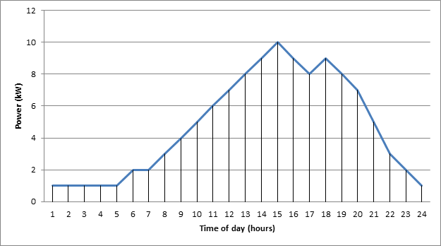
To see the relationship graphically, consider Figure 1, which could be a hypothetical load curve showing the power consumed by a household (in kW) throughout a 24 hour day. Each point on the curve indicates the instantaneous power consumed at a specific time, with a peak of 10 kW at 3pm. The area under the curve is the amount of energy consumed during the 24 hour period, in this case 113 kWh.


Figure 1 Hypothetical load curve showing Power (kW) vs. Time of day (hours).
Consider that Figure 1 could also be a graph showing the power output of an energy storage device during a 24 hour period. During this 24 hour period the energy storage device outputs a maximum power of 10 kW at 3pm and discharges a total of 113 kWh of energy. Under normal operating conditions the storage system’s maximum power output would be the “Nameplate Power Rating(DOE, 2010). Some energy storage technologies have the short term, emergency capability of discharging at power rates 1.5 to 2 times their nameplate power rating.  The value of this capability, referred to as the equipment’s “Emergency Rating”, can often offset the reduced efficiency and storage equipment damage incurred by this above nominal burst of power (Eyer & Corey, 2010).
The amount of time that an energy storage technology can discharge at its nameplate power rating, before requiring a recharge, is the “Discharge Duration”. Multiplied by the power rating of the device, this is the amount of energy that the storage device can produce. If the energy storage technology, whose power output curve is represented in Figure 1, has a nameplate power rating of 10 kW and a discharge duration of 12 hours, the energy storage device can produce 120 kWh of energy before requiring a recharge. Figure 1 demonstrates a valuable advantage of an energy storage device over traditional power generation equipment. Unlike a traditional generator, most energy storage technology can discharge at significantly variable rates, below its nameplate power rating, without incurring significant inefficiency or equipment damage (Baxter, 2006).

<< Cost of Energy Storage                                                              Time Dependent Parameters>>                                   

Works Cited


Baxter, R. (2006). Energy Storage; A Nontechnical Guide. Tulsa, Oklahoma: PennWell Corporation.

DOE. (2010, November 12). Discussion of Data for Smart Grid Metrics and Benefits; Storage System Performance Supplement. Retrieved December 2, 2012, from http://www.smartgrid.gov/sites/default/files/pdfs/energy_storage_system_performance_supplement.pdf

Eyer, J., & Corey, G. (2010). Energy Storage for the Electricity Grid: Benefits and Market Potential Assessment Guide. Albuquerque, New Mexico: Sandia National Laboratories.

Miller, K. (2012, October 26). How To Speak Data Center: Power vs. Energy. Retrieved December 2, 2012, from Network Computing: http://www.networkcomputing.com/data-center/how-to-speak-data-center-power-vs-energy/240010565


NSTAR. (2012). Residential > Rates & Tariffs > Basic Service. Retrieved December 2, 2012, from NSTAR: http://www.nstar.com/residential/rates_tariffs/basic_service.asp